Some engineering components have to operate in the most extreme conditions imaginable, so having confidence in their ability to remain structurally undamaged is paramount. ") These sorts of components are often also very expensive, usually because they make use of rare materials, complex manufacturing processes or, in some cases, both.
These sorts of components are often also very expensive, usually because they make use of rare materials, complex manufacturing processes or, in some cases, both.
Take, for example, the components found inside a jet engine. The turbine blades inside these engines are exposed to combusting gases at temperatures of over 1500°C, which is hotter than the melting temperature of the materials themselves. The materials are also subject to rotational speeds of over 13,000 rpm, placing them under considerable mechanical load.
Predicting the service lives of components in these sorts of situations is a very complex engineering challenge. The parts are very costly to construct, meaning that mere mechanical assessments would be preclusively expensive. So instead, engineers approach problems like this by dividing them into simpler, single elements.
Mechanical Properties
The turbine blades and discs (to which the blades are attached) are commonly manufactured from nickel based superalloys (see:
Making Metals Take the Heat), since these alloys have very good performance at high temperatures.
During normal operation of a jet engine, high centrifugal forces cause small amounts of deformation to occur. 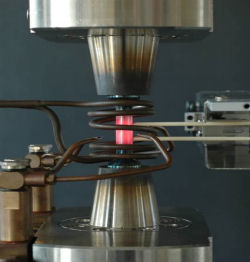 This can either be elastic deformation, which reverses when the stress is removed, or inelastic deformation, which is a permanent change in the material.
Under sufficiently large stresses, inelastic deformation can occur instantaneously. But lower levels of stress, when coupled with a high temperature, can cause a more gradual form of deformation called creep.
Also, when a metal is subjected to repeated cycles of loading, where a stress is applied and then removed, fatigue can occur. This is where the metal becomes irreversibly damaged and can fail.
Furthermore, the surrounding environment can affect behaviour of the metal. For example, oxygen in the air can lead to oxidation, and sulphur in the fuel can lead to sulphidation, especially at the high temperatures found in a gas turbine. To complicate the problem, each of these mechanisms can interact with each other (e.g. creep-fatigue interactions when fatigue occurs at very high temperature, and thermo-mechanical fatigue where thermal and stress cycles interact).
 Material Testing
To understand each of these mechanisms, laboratory tests can be carried out on specimens manufactured using the relevant material.
For example, the strength of a material can be measured by pulling it until it fails and recording the stress that was required to cause the specimen to break. By repeating this test at different temperatures, an understanding of how temperature affects strength can be obtained.
Other tests can be performed to replicate creep conditions where specimens are held under a constant stress at high temperatures for long periods of time (up to several months), and fatigue conditions can be replicated by applying alternating stresses to the specimen. The tests can also be performed in a vacuum to eliminate the effects of oxidation, or in a specific gas environment (e.g. sulphur dioxide).
For each test type, load, extension and temperature levels are closely monitored and recorded. Optical and electron microscopy are often used to examine the structure of the specimen and help to understand the microstructural mechanism of failure.
Understanding Material behaviour
Each test type is designed to develop an understanding of a particular aspect of material behaviour and by running tests at different conditions, an understanding as to how different conditions affect material response can be generated. Numerical methods are used to quantify material behaviour and help to relate material response to applied conditions.

The simplest example of a numerical method is 'Young's' elastic modulus, which relates elastic strain to applied stress.
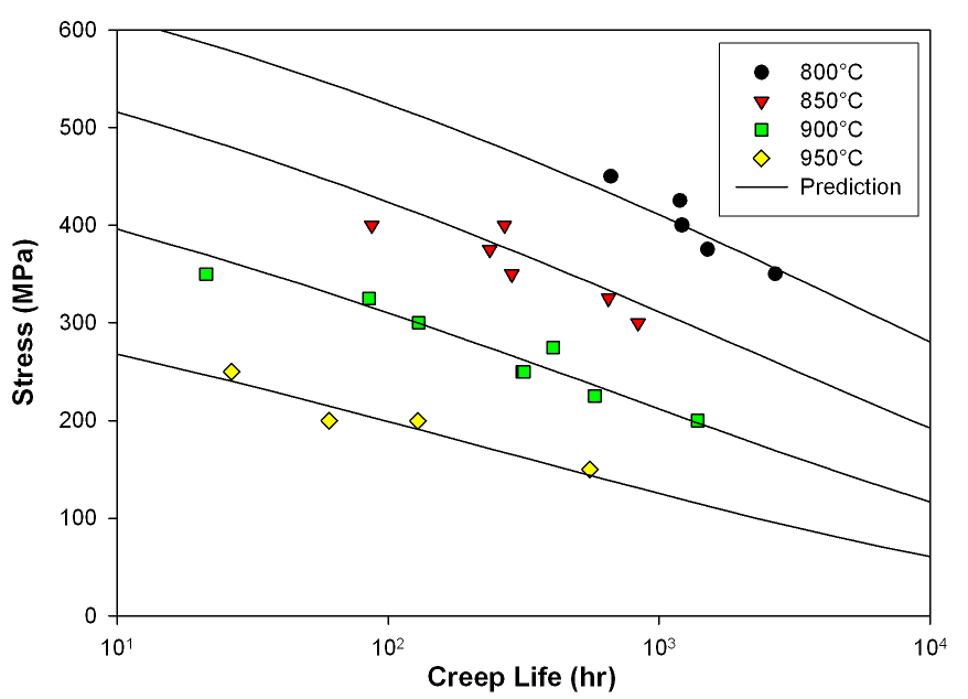
More complex equations are used to relate other material properties, such as fatigue life and creep rate, to test conditions. Some equations are purely empirical and are used as they represent test data, whereas other methods are based on microstructural observations.
Finite Element Modelling
Whilst the above methods are adequate for relating the behaviour of simple test specimens to applied conditions, in reality, components such as those found in gas turbines have complex shapes that result in uneven loads and temperature distributions. To predict the behaviour of these complex structural components, the finite element method (FEM) is used.
This is a computer based numerical technique used to solve systems of equations, and since modern computers are capable of billions of calculations per second, FEM is a very powerful tool for engineers.
A structural finite element analysis is run by taking the geometry of a component and splitting it into a number of elements. Each element is then given material properties (such as Young's modulus and thermal conductivity) and is connected to other elements by nodes. Test conditions such as load and temperature are applied and the model is run in a number of small time steps. Since the conditions at points within each element are considered to be constant for each time step, the equations derived from mechanical testing can be applied and the material response can be predicted. Using this method a prediction of the material response of the whole component can be estimated.
- Previous Can my dog give me diarrhoea?
- Next Predicting the Genomic Future


 crystal")

Comments
Add a comment